The time has come to work on the deck edge and deck. You will need several sheets of 1/8"x12"x24" or 48" 5 ply aircraft plywood, a compass, sharp pencil, and either a band saw or jig saw. You also need to decide whether to make the amidships casement gun area integral with the hull or the deck. I chose to make mine a part of the hull, and here I'll show you how.
By either taking measurements from the plans and drawing them on a 1/2" thick piece of hardwood, or by photocopying the casement section of the plans and pasting them to the wood, transfer the casement lines so you can cut out the casement section with a band saw, the back of which should be cut straight at a depth equal to the subdeck width. A layer of 1/8" wood will fit under this casement, make it as wide as the subdeck as well and as long as the distance between the first and last "zig" in the casement. (Photo 24 - Note: You'll notice I used 1/4" plywood for this section because of a mistake in the plans and I didn't catch it until I found some good photographs.) Clamp the two pieces together and then drill two 1/8" holes through both and insert 1/8" dowels to hold them together. Repeat for the other side.
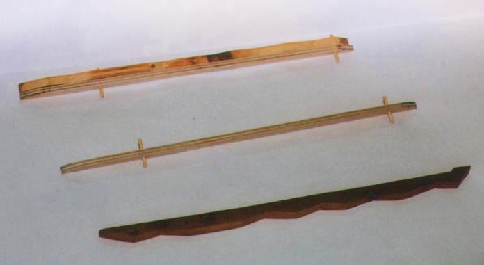 Photo 24
Position one casement assembly in its proper place on the subdeck and then clamp. Remove one wooden dowel and, by drilling down that hole, drill a hole in the subdeck. Replace that dowel, now going all the way through the subdeck and repeat for the second one. Then repeat for the other side of the ship. The reason for not gluing this section in place just yet is that this will allow you to raise the casement section up and fit the deck edge pieces coming from the bow and stern under the "zig", hiding the butt joint. Remove these sections so you can draw out the deck edge.
To start the deck edge I placed the hull upside-down on a sheet of 1/8" plywood and traced the bow and stern portions. I then took a compass set for 3/8" to 1/2" and traced a line inside the first, these inner pieces will make up the actual decks. There are two ways to handle the extreme forward and aft parts of the deck, either make the decks real long with a continuous deck edge around the bow and stern, or make shorter decks with removable sections at the forecastle and quarterdeck. (Figure J) When combined with the decks that hold the gun barbettes and superstructure, this makes a total of five deck pieces, and is the method I decided upon. (Picture 25 shows the two removable sections in place and the three other decks, "A" being the forward gun deck,"B" the superstructure or mid-deck, and "C" the after gundeck, in front of the ship. Under the ship you can see the original "Option 1" stern deck edge that I was originally thinking about using.) I found it easier at lakeside to wrestle with the two shorter decks and the superstructure than with two longer decks, and I didn't normally need immediate access to the areas covered by the fore and aft pieces. We'll first install these pieces.
 Figure J
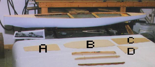 Photo 25
Trace and cut out two pieces of 1/8" plywood for bow and stern. Lay the deck on the sub-deck and drill in three holes through the deck into the subdeck, one at the fantail, the to either side near the forward edge. Remove the deck and then drill out the holes in the subdeck so that they will just accept the neck of a 4/40 or 6/32 blindnut (your choice - I used 6/32). Insert a like size bolt down the hole, match with the top (points up) part of the blind nut under the deck so they mesh, then start screwing the bolt into the blindnut. As you turn the bolt the blindnut will rise up (you'll have to hold it so it doesn't spin) and then get a bite in the bottom of the subdeck. Keep turning the bolt till the blindnut is tight against the bottom of the subdeck. Unscrew the bolts and reset the deck and sand to shape. Now take the aft gun deck and carefully cut it out along the inner lines drawn above. Then fit it onto the hull forward of the quarterdeck section and mark where the cross cut will be. Make this cut and set the deck in place. Using the sheet of 1/8" ply you used to cut the gun deck from, cut out strips of wood 1/8" outside of the outer line you had originally drawn. This piece, with appropriate sanding to get a nice fit, will become the aft deck edge. Set it in place on the subdeck, trim aft portion so it fits neatly with the quarterdeck, then install the casement section for that side and note where the 1/8" layer of the casement section ends, cut and sand the forward section of the deck edge to butt neatly against this area, the projecting part of the casement hiding the seam. Sand the subdeck and bottom of the deck edge, then epoxy/clamp into place. Repeat for the other side of the hull, (Picture 26 shows the completed aft deck edge and quarterdeck - the casement section has not yet been epoxied into place and won't be until the forward gundeck and forecastle decks are in place.) Repeat these procedures for the forward gun and forecastle decks. (Picture 27)
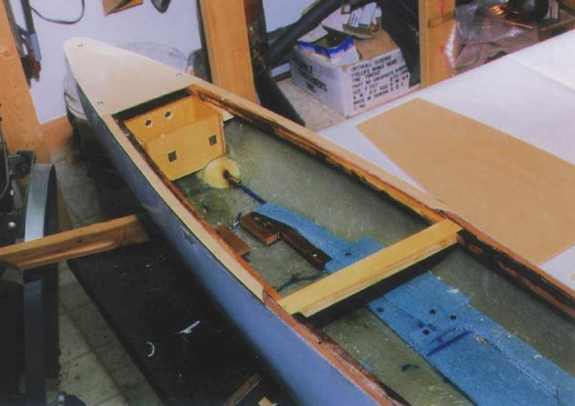 Photo 26
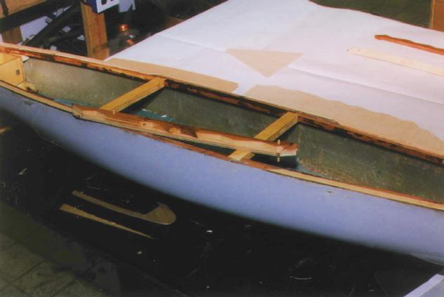 Photo 27
With the forward and aft gundecks in place you now need to epoxy the casement section into place, then decide where to place the outlet for the pump. I drilled a hole through the last flat portion of the starboard casement section and built the outlet into the wood. I then set the mid-deck on top and fit it for its deck edge. The forward section will hang out over the forward gun deck. (Photo 28), while the after portion of the mid-deck (Deck "D" in Photo 25) will go aft. The after section is easiest to start with. With the mid-deck in place, measure the height from the after gundeck to the bottom of the mid-deck. Cut several pieces of 1/4" hardwood to this height to use as bulkheads and epoxy them into place as the support for Deck D. Drill two 1/8" holes through the top of each side piece down through the aft gundeck and then insert/epoxy a 1/8" dowel to added strength. Trim the top and bottom ends of the dowel, and on top of this structure place Deck D and epoxy into place. (Photo 29)
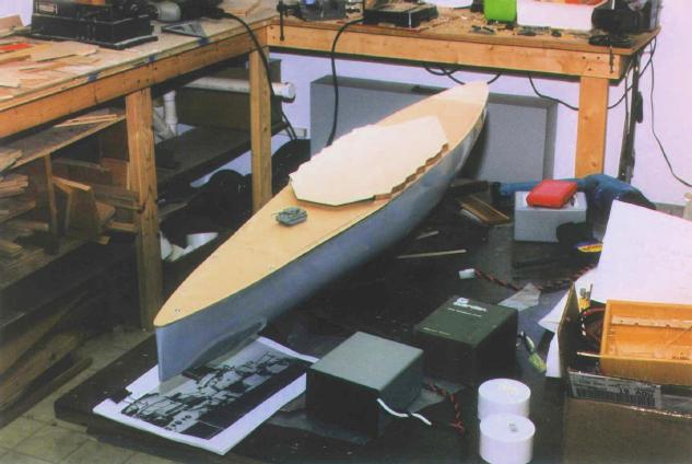 Photo 28
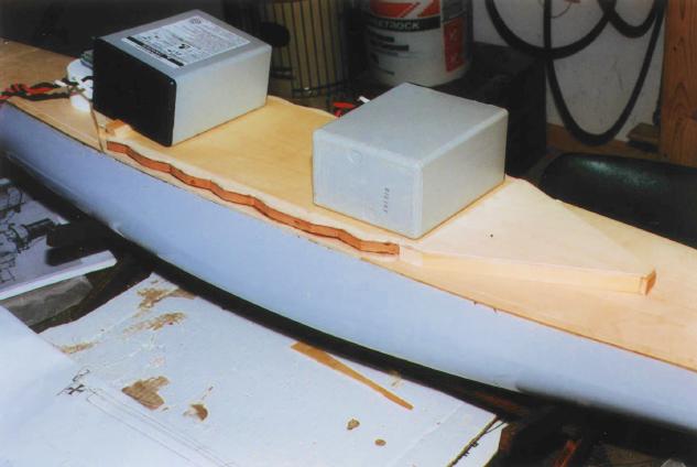 Photo 29
Completion of the forward portion of the mid-deck is similar, but complicated by the presence of "B" turret's barbette. For my barbettes I used 2" PVC blind caps with flat tops. With just a little sanding they equal the diameter of the Derfflinger classes 12" turret barbettes. Measure the distance from the bow to the center of "B" Barbette as shown on the plans, mark the spot along the centerline on the forward gundeck and the mid-deck. (You can also mark out the other barbette locations at this time.) Using the compass draw a circle at each spot of the same diameter as the PVC cap after sanding. Using a rotary or jig saw cut out the indent for the barbette in the mid-deck, then finish with a file and sandpaper. Set the mid-deck in place and fit two pieces of 1/4"-1/2" thick hardwood as bulkheads as you did for the aft gundeck. The ends that protrude from under the mid-deck will need to be shaped with an inward curve to accept the barbette. (Photo 30) Now cut out the hole on the forward gundeck for "B" barbette and epoxy the barbette into place. (Photo 31 and Photo 32 show the deck with all holes cut.) The top of all the barbettes should be level with the horizon, not the deck, which should rise up as you go forward. Again drill 1/8" holes and insert dowels to secure the bulkheads to the gundeck and to the barbette. Remove the excess wood deck aft of the barbette at the gundeck level if you like, it will save you some weight (you can do this to the aft gundeck below the mid-deck as well.) Epoxy and shape in place a deck-edge on top of the wooden bulkheads, making sure you get a nice fit against the barbette. Remove all the deck pieces, and using 24 hour epoxy coat all of the exposed wooden surfaces (above and below decks, behind bulkheads, and on/under the subdeck) as a water sealant and let dry. Ensure you don't get too much in the corners of the deck edge or you'll be sanding/filing for a while to get the decks to fit into place again, and remember to put something into the blindnut holes to keep the epoxy from clogging them (I coated the bolts with Vaseline and screwed them into place.) (Photo 33 and Photo 34 show barbettes mounted in the now sealed decks.)
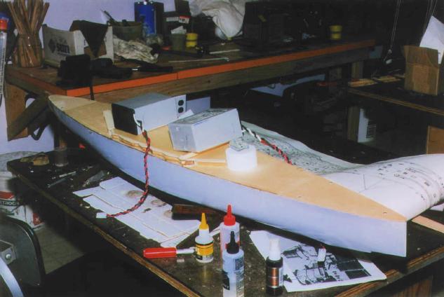 Photo 30
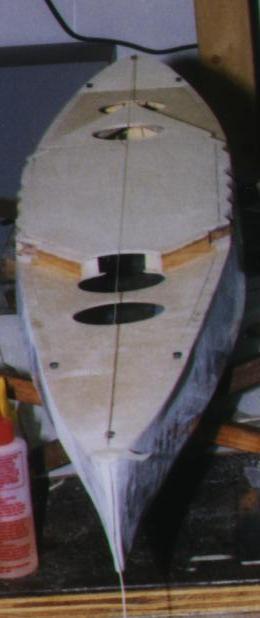 Photo 31
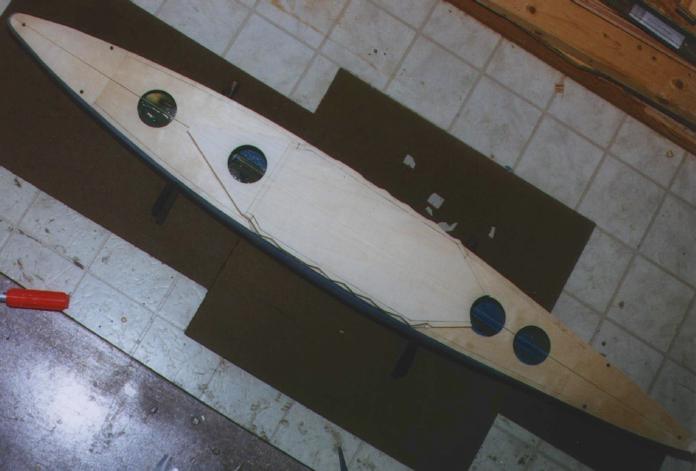 Photo 32
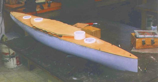 Photo 33
 Photo 34At this point you should have completed the watertight radio and rudder boxes, propeller shafts and rudders, and completed wiring of the motors and pump. By this time you should have chosen and purchased your main (and, if separate, receiver) batteries. And now you have a deck. Guess what, you're ready to go to sea.
Assemble all the above listed components and bench test each to ensure operability. Install the components in the hull, put Vaseline and the propeller shafts into the stuffing tubes and attach the propellers, hook up the rudder to the rudder servo, test that the rudder turns the way you want when you move the stick, the motors go the direction you want (Optimally, when you push forward on the stick and the boat goes forward, the port propeller turns counter-clockwise, the starboard clockwise - this "throws" the water up and back against the hull and rudder giving better maneuverability.), and that the pump turns on and off. Take the radio and the assembled boat to a local pond or a pool, and by the way, bring a magic marker.
Place the boat on the water, put your CO2 regulator in the bow for weight if you have it, turn on the transmitter (always turn on the transmitter first when starting up, and turn it off last when shutting down), and then plug in the main (and if separate, receiver) batteries. While holding onto the boat run the motor to ensure it goes the way you want, and actuate the rudder to ensure it goes the right way. Test the pump. Pour some water into the boat and ensure the pump picks it up and spits it out. Let go and carefully run the boat being careful not to get too much water into the hull at this point. Leave the pump on to be sure. Enjoy yourself for a while. When you've had enough bring her back to shore - it's time to work again.
With the ship in the water, mark at the bow and stern where the waterline is. Is it where it should be? Is the ship level fore-aft and port-starboard? If not, adjust the positions of the battery(s) and radio box locations till she is floating how you want. Use the marker to trace the positions of the battery(s) and radio box, then disconnect the power to the boat and turn off the radio transmitter, it's time to go home.