In this section we're going to wire up the motors and build and outfit the radio box. First the motors.
For the Derfflinger class I recommend 600 series 6 volt motors for the propulsion system and pump, the cheapest you can get. Huh?? Yep, get cheap ones. Remember that the purpose of this hobby is combat. No use ruining $10 motors when you get sunk. I used H&R 600's that cost about $0.75 each when bought in bulk. To make it easier to replace and or test systems they are all wired the same. Each motor gets one red 14 gauge stranded wire soldered to the positive terminal, one black 14 gauge stranded wire soldered to negative, and one 0.47 micro-farad capacitor soldered across the terminals to limit radio interference. The positive terminal is normally denoted by a circular indent in the casing. The ends of the wires have female .093 pins soldered on that are inserted into female nylon connectors (the brand name is Molex) bought at Radio Shack or any electronics store. The positive terminal goes in the hole closest to the pointed end. The batteries you decide to use (I used two Powersonic 6 volt 12amp/hr gel cels) should be wired with male 0.93 pins, positive wire in the hole closest to the pointed part of the male nylon connector. An easy way to remember this is that "the male gets the power", i.e. the male connector comes from the battery and the positive wire goes in the hole closest to the point of the connector.
With the batteries and motors wired we move onto the radio box, the heart and soul of your ship. Here everything comes together, the throttles that control the motors, poppets that fire the guns, the receiver that tells the servos what to do. Radio boxes come in all sizes and styles, each custom fitted to the ship and radio components being used. I'm going to provide a general overview of the construction of a solid, water tight radio box, you will have to adjust what I tell you for your tools and systems.
First you need to decide whether you are going to use poppet valves or solenoids to fire your guns. Poppet valves are mechanically actuated air valves that allow the CO2 to get from the storage tank to the gun. Solenoids do the same job, but are electronically controlled. Each has its advantages. Poppet valves are cheap (about $5.00 each) and simple to troubleshoot. Solenoids do not need to be placed within or on the radio box, thus allowing them to be placed closer to the guns. The downside of poppets are they can only control one gun, while solenoids can be set to fire from the same firing circuit. Solenoids on the other hand are heavy and expensive ($25.00+ each), and if the system is not properly shielded they may interfere with the radio. For the Derfflinger, the best choice in terms of cost and weight is a poppet valve system.
To fire the Derfflinger's three guns we need three poppet valves, and to control the motors and pump we need three 15amp switches, along with four servos and the radio receiver. I used Clippard MAV-2 poppet valves, GC Roller Switches, Airtronic's 102 servos with their VG6R 6 Channel FM Receiver, and 14 gauge wire for the internal connections to the switches. The box is made from 1/8" 3 or 5 ply plywood and is approximately 3" deep to accommodate the servos and wiring, about 6" wide and about 4" long. Like the rudder servo box the servo mounts here are also mortised into the sides of the box for strength and to leave room under the servos for wires, with wood inserts placed at the corners to hold the securing blind nuts. (See Photo 21 and Photo 22 - NOTE: The smaller box is one I was working on for the refit of my South Dakota. The smaller size is obtained through the use of micro servos and small switches actuating solenoids. The refit is another story for another time, like, when I actually complete it!) The switches are removable, mounting on 3/16" dowel rods set into 1/8" plywood inserts that fit between the servos and are screwed down with the servo mounting screws. The cams on top of the servos are held in place with #0 wood screws, coming from the bottom through the plastic horns, with the ends of the screws sanded off after completion. (See Photo 23)
 Photo 21
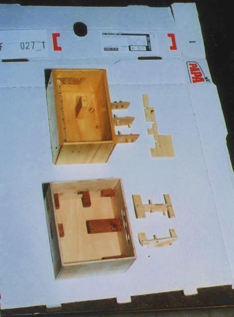 Photo 22
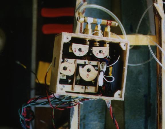 Photo 23
To move the gas from the tank to the individual poppet valves you need a method to distribute it. One simple method is to use a Clippard "X" coupling with four 10-32 female ports drilled into it. Into one port insert a 10-32 to 1/8" Hose Fitting, into the others fit 10-32 to 1/16" Hose Fittings. A more complicated method is the one I used, but it requires the use of a lathe. Use the lathe to bore a 1/2" hole down 9/10's of a 3 inch long, 3/4" diameter solid brass rod. File or sand a flat area down the length of the rod, then mark the center of the rod on the flat spot. Then place marks 3/4" on center to either side. Drill holes at these points and then tap for 10-32 threads. Blow out any metal from inside the rod, , then solder a piece of 1/16" brass sheet over the end and drill/tap a 10-32 hole. This is now your distribution manifold. Insert a Clippard double male short coupling into each of the three holes, then screw a poppet valve onto each coupling so the exhaust ports all face down. Into the side of the box that faces forward drill three 5/8" holes, 3/4" on center about 1 1/8" from the top. The poppet valve/manifold assembly should fit into these holes from the outside, inside use the provided flat nuts to secure it into place. (Before final assembly fill the voids between the poppet valve threaded section and hole with silicon.) The servos inside should be mounted so the horn is centered between two valves, and to a depth that allows the cams to press the valve stems in fully. The lid of the box is made in the same manner as the rudder servo box in the previous section.
How you wire the interior of the box will depend on whether you chose poppets or solenoids, and the manner of speed control you chose. With poppets there is no wiring to the firing circuit except for the three piece wire for the actuating servos, and the speed control in this case is the MAG Throttle.
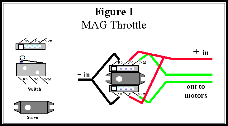 Figure I
The MAG Throttle is basically two switches wired exactly alike so that, when neither switch is depressed, they short each other out. The positive wire for each switch is attached to the Normally Closed (NC) contact on the switch, negative to the Normally Open (NO) contact, and a neutral colored wire, in my case green, wired to the Common (COM) contact. (Figure I) For quick replacement solder female spade wire connectors to the wires of the proper size to attach firmly to the contacts. The two switches are fixed to either side of a servo, either directly to the servo or mounted separately, my method is described above. This is how the MAG Throttle works.
When both switches are in the up (not depressed) position, negative current is being sent to both COM contacts, so no current flows. When you depress one switch, positive current from the NC contact of the depressed switch flows out the COM contact and negative current comes from the NO switch through the COM of the up switch. The two green wires are connected to the motors, and so current flows to the motors causing the motor to turn, say, clockwise. Release the depressed switch and the short condition is re-established - the motor stops. Depress the other switch and the motor will turn again, only this time in the opposite direction, counter-clockwise.
When laying out how to run the wiring in the box, to keep the wires straight I suggest that wires bringing power into the radio box be set to one side of the box, wires taking power out to various systems come go out the other side. (Photo 23 shows the main power and receiver power wires going in from the bottom left, while the wires leading out to the pump and motors come out of the bottom left.) There are four different sets of wire you will need to account for or install when fitting out the radio box.
First is the receiver power source wiring. You can either run the receiver from the main battery(s) or from a separate battery. I ran my receiver from the 4.8V battery that came from Airtronics with my radio. If you run the receiver from the main battery(s) you will need to be concerned about radio interference being transmitted from the motors to the receiver, causing possible control problems. Either way you will need a male connector that will fit into your receiver's power outlet pre-wired with at least 8 inches of wire. Install the servos, switches, and receiver into the box, then determine where the power wire will need to enter the box to connect into the receiver. If you intend to use a separate battery, drill a hole at this location that is just larger than the diameter of the wire, then thread the wire through and attach a female connector that will match that on the separate battery. If you are going run the receiver from main power (directly from the large battery(s)), shorten the wire to about three inches and splice it into the positive and negative wires after they enter the radio box. The best place is at wherever they split to go to the individual switches.
Second is the power wiring for the motors/pump. Drill separate holes for the positive and negative wires, then thread them into the box. Solder three short (3-5") lengths of 12 gauge wire to the interior end of the positive main power wire (make sure the color of the extensions match the color of the wire) and attach them to the NC contacts of all three switches; two short and one long (10-20" - needs to reach from the radio box to the pump)) lengths to the negative wire, then solder female spade connector to the ends of all the newly added wire except on longer piece of negative wire and attach the spades to the NO contacts of the throttle switches. The longer wire gets a separate hole drilled in the box for it and it then exits the box to lead to the pump. Remember to place shrink tubing or liquid electrical tape over the solder joint to prevent a short. A length of positive wire is then inserted through a hole in the box, a female spade soldered on, and the spade connected to the COM contact of the pump switch. Outside the box male pins and a male Molex connector is added to these two pump wires. The green wires have hole drilled through the box and are threaded through, then spades soldered on and the wires attached to the COM contact of both throttle switches. The exterior ends of the green wires need to be long enough to reach to the motor wires. Solder short extensions of wire to each green wire, equal to the number of motors to be powered, then solder male pins and mount a male Molex connector that will have one extension from each green wire.
Third is the radio antenna wire. I soldered a male spade connector to the end of the antenna, then ran a wire through the box, soldering a female spade to the interior end and another male to the exterior end. A length of 22 gauge wire served as the antenna and had a male spade soldered to it to hook up to the radio box wire.
Fourth, the servo wires need to be routed around the interior so they do not interfere with the actions of the servos or switches, as well as being able to be plugged into the receiver. With this all that is left is sealing all of the holes around the wires with epoxy and silicon to keep water out, then fitting the box for a lid and sealing it closed as was done with the rudder servo box.
Next lets build the Deck Edge & Deck.