Using the plans and an indelible magic marker, mark the interior of the hull with the locations of the main gun barbettes and rudder post locations. This will allow you to determine where to place the motors and rudder servo so they won't interfere with gun placement. Epoxy a 1/4" tall piece of solid wood to the interior of the hull at the location of the rudder, then drill a 3/16" hole through both for the rudder post. Insert a 6" length of 1/8" ID brass tubing, making sure you have plenty of tubing both inside and outside the hull, and epoxy into place. (Photo 8) Repeat for each rudder. In the case of the Derfflinger, two posts were installed, one forward of the other. The size of the wood pieces you will need to build the rudders is dependent upon the class of ship you are building. Under IR/CWCC rules, a Derfflinger class battlecruiser is a Class 4 ship and is allotted 2-1/2 square inches of rudder area. But she also had two rudders, which allows for an increase in area by 50%, for a total of 3-3/4 square inches. For better maneuverability we will concentrate most of this area on the aftermost rudder (behind where the propellers would be); the forward rudder is mainly decorative but is required by the rules to be functional.
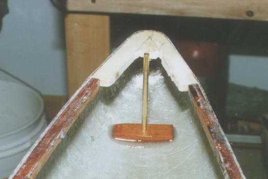 Photo 8
To build the rudder you need some pieces of 1/8" plywood a little larger than the size of the rudder you want to make (in this case 1.5"H x 2.5"L) and a 6" length of 1/8" brass rod. Bend the last inch of the rod 45 degrees, then trace this shape on the middle piece of wood. Cut out this shape, then insert the rod into the slot. Epoxy the other two pieces to the sides of the first, then sand to shape. (Figure F) The forward rudder can be made by soldering a very small piece of brass sheet (about 1/8"L by 1/4"H) to a 3" length of 1/8" brass rod. Set these aside for later.
 Figure F
Now we decide where to place the motors and pump. We've already marked out where the aft turret/barbettes (and hence the guns) will be placed, and we now know where the rudder posts are. The motors must be in a position to drive the propeller shafts without binding, so they should be mounted low in the hull and far enough forward to keep the shafts from having to be placed at too steep of a down angle. Motor mounts come in all kinds of designs, from store-bought to home-made. Since a working combat warship see's harsh duty a mount that allows quick access to check and/or replace a motor is essential, and for simplicity direct-drive to the shaft is very popular. One mounting method is to just use a removable adhesive such as "Goop" to glue the motors to the bottom of the hull. Other members glue hose clamps to the bottom of the boat and then use the tightening screw on the clamp to secure the motor. I placed my propulsion motors between the "C" and "D" (rearmost) barrettes since this kept the gun areas free down to the bottom of the boat. I built my mounts from 1/8" aluminum and 3/8" cedar in a compact arrangement that puts my pump and motors all together.
Photo 9 and Figure G show the a general plan for the parts I made - actual sizes will vary with the type and size of motors you use, the diameter of the pump casing, and the how high or low you want the motors mounted. As with the pump casing you'll measure and drill holes for the motor shaft bearing and mounting bolts and use #4-32 or #4-40 bolts to attach the motors to the motor mount, then #6-32 bolts to assemble the mount with the base plate and bases. The "L" shaped pieces are the bases, made of cedar, with the bottom 3/16" of each hole drilled out to 3/16" to accept #6-32 blind nuts without splitting the wood. Before hammering in the blind nuts, sand the bottom of the bases to match the contour of the bottom of the hull. The aluminum motor mounts and base plate were cut using a hacksaw, the rough edges taken down with a flat steel file. The elongated holes are made drilling one 1/8" hole at each end then filing out the rest using a round 1/8" file. The entire assembly was test fitted outside the boat, then the base plate and wood base were bolted together (the end of the bolts should not protrude from the blind nuts). The location for the base needs to be thoroughly sanded, then the wood base (with base plate attached) is epoxied to the inner hull using 6 or 15 minute epoxy. Place a battery or weight on the base plate to press the base to the hull and get a good bond. The completed assembly fits nicely between the two aftermost turrets. (Photo 10 & Photo 11)
 Figure G
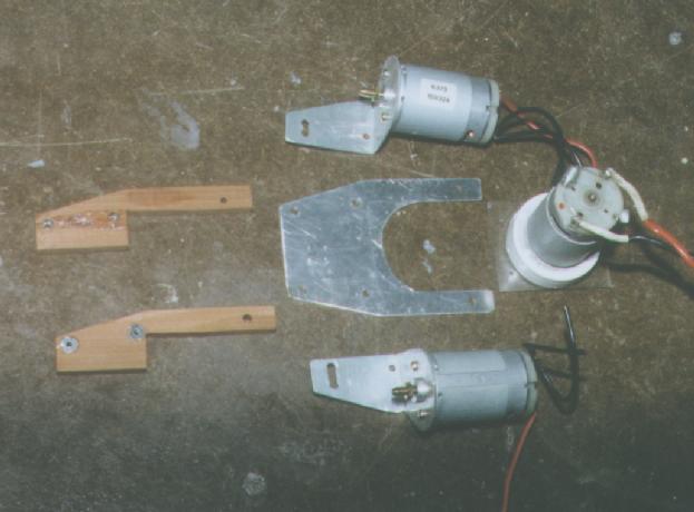 Photo 9
 Photo 10
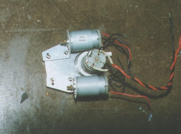 Photo 11
Once you have mounted the motors the next step is to build the stuffing tubes for the propeller shafts. The stuffing tubes allow the rotating propeller shafts to penetrate the hull without letting water in. To build your stuffing tubes you need to measure the distance from the end of the motor shaft to the rudder post. Subtract three inches for the shaft joints, 1/2 the length of the rudder (in this case 1.25"), one inch for propeller clearance, and then one inch just to be sure it's not too long. Cut two equal lengths of 3/16" ID brass tubing, just a little longer than your sum above, and four 1" lengths of 1/8" ID tubing to act as bushings. (Photo 12) Flux and solder one 1/8" ID bushing into each end of the two 3/16" ID tubes, cool, and then cut the ends off flat. (Photo 13)
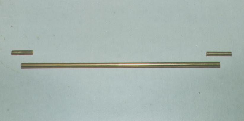 Photo 12
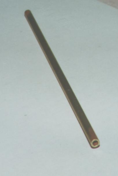 Photo 13
Inside the hull, measure forward one inch from your aftermost rudder post, then measure 1 to 1-1/2 inches out toward each side and make a mark. Using a magic marker and a ruler, draw a guide line from those marks to the matching motor shaft. This shows the direction the stuffing tube is going to go as it penetrates the hull. Angling the shafts, and thus the propellers, toward the rudder increases the water flow over the rudder and enhances maneuverability. (Photo 14) Approximately 6 - 8 inches forward of the aft rudder post drill two holes along the guide line about 1-1/2" apart. Use a round file to remove the material between the holes, then insert one stuffing tube. Secure the tube on the outside of the hull with tape or clay at the correct depth, angle and distance (inside end should be about three inches from the end of the motor shaft and the outside end should be one inch plus 1/2 the rudder from the rudder post). (Photo 15) Also tape over the outside of the opening to keep the epoxy we will use to secure the tubes from running out. Repeat for the other stuffing tube and align them to the same depth. Once the stuffing tubes are in position, mix some 24-hour epoxy with either Kevlar or fiberglass fibers to create a paste. Place a liberal amount of the paste around the inside portions of the shaft. To give the joint a smooth finish drape a layer of fiberglass cloth over the paste and soak with epoxy. Use any extra paste to fill in the gap in the center bottom of the hull forward of the rudder post to channel water forward to the pump. (Photo 16) Let dry 24 hours. When the interior is dry, cut the rudder post at the height the propwash from the propellers would cross it. Mix up some more paste and apply to the exterior of the hull around the stuffing tubes and aft rudder post (forward rudder post should be cut almost flush with the hull). Again cover with fiberglass cloth and let dry. (Photo 17 & Photo 18) Secure the end of the stuffing tubes to the hull using large cotler pins, the round end fitted around the tube and the stems inserted into holes drilled into the hull and epoxied into place.
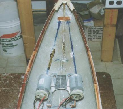 Photo 14
 Photo 15
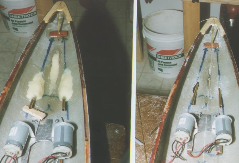 Photo 16
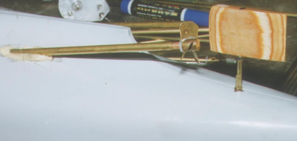 Photo 17
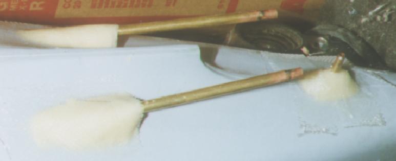 Photo 18
Install the motor assembly, mounting one Dumas 1/8" Shaft Brass Universal Socket to each motor shaft. Insert a length of 1/8" brass rod into the stuffing tube from the exterior. Once the inside end appears, mount a socket onto the rod, then insert a Dumas 1" Nylon Coupling Rod between the two sockets and press toward each other. Outside the hull the rod should be marked for cutting at a point that will place the propeller just forward of the aft, main rudder. Remove the shaft, cut it to the marked length, then do the same for the other shaft. Use a flat file to flatten the last 1/4" of both ends of each shaft to give the socket and propeller set screws something to "bite". Using an irrigation syringe filled with Vaseline or other lubricant (I used high temperature brake grease) squeeze some into the stuffing tube, then assemble the entire drive train and install the aft rudder. Apply power to the motors and check for binding, vibrations, and rudder clearance, adjusting the angle of the motor mounts until the system runs smoothly.
Remove the rudder(s) and cut the inside portion of the rudder stuffing tubes to within 1/2" of the inside hull or support. Reinstall the rudders and mark them for cutting 3/4" above the top of the rudder tubes. Remove, cut, and file the ends as was done to the propeller shafts. To control the rudders you can use gears or control rods. I've never used gears (not yet anyway) so I'll show you how to mount the rudder using control rods that move commercially available or home-made rudder horns mounted on the rudder shaft. To make them yourself you'll need 3/8" brass rod, a 6"x3/8"x1/16" piece of brass sheet, a lathe, a hacksaw, and your soldering gear. On the lathe flatten one end of the brass rod, then drill a 1/8" hole down the center to a depth of about 1". While the rod is still turning cut use the hacksaw to cut off two 1/2" pieces. Use the lathe to flattened both ends of each piece so they have a smooth finish. Using tin snips or a cutting wheel cut two 1" long pieces of the brass sheet, then solder one piece to one end of each piece of brass rod. Use a drill to continue the existing 1/8" hole in the rod through the now attached brass sheet, then drill a hole for the set screw in the side of the rod, and finally drill two or four 1/16" holes in the brass sheet equally distance from the main 1/8" shaft hole. Tap for and insert the set screw, then mount the horns onto the rudder shafts.
How you mount the rudder servo is another item in which you have a choice. Some people will water-proof their servos and install them directly into the hull with no other protection. I prefer to install my servos in a watertight box made just to hold the servo with the control rods exiting the box via rubber bellows. The rudder box is made of 1/8" plywood on all sides but the top, large enough to accommodate the rudder servo and allow free travel of the servo horn. I built the sides of my box so they extended beyond the bottom so I could fit them to the shape of the hull while keeping the box on an even keel. This also allowed water to move freely under the box down to the pump inlet location between the motors. I drilled two 1/2" holes in the after portion of the box (as wide apart as the width of the servo horn), then cut a slit from the top edge to the apex of each hole with a jewelers or hobby jigsaw to facilitate installation of the control rods. (Photo 19) Finally I pre-drilled and then installed/uninstalled the bellows so they would be easier to install when the box was in the ship. At the corners I epoxied in small squares of wood, then fitted a Plexiglass top and secured it in place temporarily. Drill through the top and the corner pieces with a 1/8" drill bit, remove the top, then drill out the holes in the wooden inserts so that a 6-32 blind nut will fit from below. Insert a 6-32 bolt and, while holding the blind nut in place, screw in the bolt so that the blind nut rises up and seats into the bottom of the wood. Remove the bolt, then test fit the lid by placing it on top of the box and bolting it down.
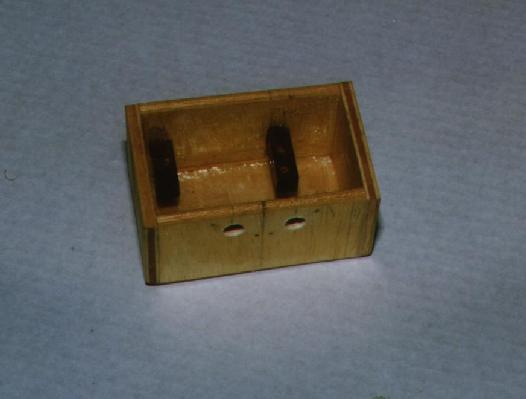 Photo 19
To mount the servo I determined the length of the servo and the distance between mounting holes, then mortise-fitted two 1"x1/4"x3/8" pieces of cedar into the forward bulkhead of the box so the servo fit cross-wise with the horn on the centerline. The servo fits between these two pieces, with the servo mounting screws being drilled into the top of them and the servo control wiring fitting under. The servo control wire then goes over the top, aft edge of the box via a small indent filed into the top rim. When sealing the box up prior to battle place a bead of silicone around the rim and into each of the four holes in the lid, then screw it into place. (Figure H is a drawing of the box and Photo 20 shows the finished box mounted into the hull.)
 Figure H
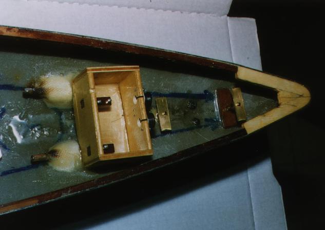 Photo 20
Use piano wire, control rod wire, or any relatively stiff wire connect the servo horn to the aft rudder horn. The wire must go through the bellows and bellows retainer, then through the hole in the box, then attach it to the horns. Repeat for the other set of horns (servo to aft rudder). Connect the bellows to the box with the provided screws and retainer, then connect the aft rudder horn to the forward rudder horn. Test of the servo movement should result in both rudders moving in the same direction. At this point empty the box of the servo and control rod assembly and remove the propeller shafts and rudders.
In the next section we will wire the motors and build and outfit the Radio Box.